

This guide covers connecting a Texas Instruments AWR6843ISK / IWR6843 60 to 64 GHz FMCW millimeter-wave radar evaluation module to a RemoteRF server or host over USB. Support is included in the built-in ti_awr6843 schema.
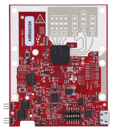
Overview
RemoteRF supports the TI AWR6843ISK / IWR6843ISK through the built-in ti_awr6843 schema. The board connects to the host over USB via an onboard dual USB-to-UART bridge, exposing two serial interfaces:
- CLI Control Port (
115200baud): Used to send radar configuration and control commands. - Data Streaming Port (
921600baud): Used to stream point-cloud and range-azimuth heatmap frames.
device_type:ti_awr6843- Firmware: TI mmWave SDK 3.x Out-of-Box Demo flashed in functional mode (
SOP = 001)
1. Install Dependencies and Detect Serial Ports
Install pyserial and Configure dialout Permissions
Ensure pyserial is installed and the user running serverrf or hostrf belongs to the dialout group:
pip install pyserial numpy
sudo usermod -aG dialout $USER
Inspect Persistent /dev/serial/by-id/ Paths
Plug the radar’s micro-USB cable into the host and inspect /dev/serial/by-id/:
ls -l /dev/serial/by-id/On an AWR6843ISK with the Silicon Labs CP2105 bridge, you will see two interfaces sharing a hardware serial number:
usb-Silicon_Labs_CP2105_Dual_USB_to_UART_Bridge_Controller_00F48B9B-if00-port0 -> ../../ttyUSB0
usb-Silicon_Labs_CP2105_Dual_USB_to_UART_Bridge_Controller_00F48B9B-if01-port0 -> ../../ttyUSB1if00(/dev/ttyUSB0) is the CLI port (115200baud).if01(/dev/ttyUSB1) is the Data port (921600baud).
2. Configure devices.yml
The ti_awr6843 driver can auto-detect the CP2105 / XDS110 port pair automatically (auto_detect: true), or you can pin a specific board by USB serial or explicit /dev/serial/by-id/ paths in devices.yml:
devices:
  - device_id: 20
    device_type: ti_awr6843
    name: TI_Radar
    init:
      auto_detect: true
      firmware_profile: "xwr68xx_oob_sdk3"
If multiple TI mmWave boards or other USB-UART devices are attached to the same host, pin the ports explicitly:
devices:
  - device_id: 20
    device_type: ti_awr6843
    name: TI_Radar
    init:
      cli_port: "/dev/serial/by-id/usb-Silicon_Labs_CP2105_Dual_USB_to_UART_Bridge_Controller_00F48B9B-if00-port0"
      data_port: "/dev/serial/by-id/usb-Silicon_Labs_CP2105_Dual_USB_to_UART_Bridge_Controller_00F48B9B-if01-port0"
      cli_baud: 115200
      data_baud: 921600
      firmware_profile: "xwr68xx_oob_sdk3"
You can also add the radar using the serverrf devices add CLI (interactively or by CP2105 USB serial):
# Interactive guided wizard on the server:
serverrf devices add ti-mmwave

# Or non-interactively by CP2105 serial:
serverrf devices add ti-mmwave "TI_Radar" --serial 00F48B9B --id 20
3. Verification
- Start or restart the RemoteRF service (
serverrf -sorhostrf -s). - Confirm that
TI_RadarshowsONLINEin the server status output. - Reserve the device and verify CLI communication and point-cloud capture from Python:
from remoterf.drivers import ensure_driver

TOKEN = "TI_Radar@ucla"
ensure_driver(token=TOKEN)

from remoterf.drivers.ti_awr6843 import TiMmWave

radar = TiMmWave(token=TOKEN)
print("Version:", radar.query_version())
radar.start()
cloud = radar.capture_point_cloud(timeout=1.0)
print("Captured frame:", cloud["frame_number"], "Points:", cloud["num_points"])
radar.stop()
radar.close()
Next Steps
- See the TI mmWave Radar Client Guide for 3D point-cloud and range-azimuth heatmap examples.
- Return to Device Setup Overview.